In our studio, we come across many types of audio cables and connectors. Each has a specific function and use, though the names of some of these can be confusing at times. Musicians, DJ’s, Music Producers, recording engineers, Mixing and Mastering Engineers and Audio engineers alike all use these cables and need to be in the know. From TRS, XLR, Phono and many others, we will understand what they are and why they are used, but first, let’s understand the basics, starting with wires.
What is a Wire?
Flexible strands or rods of metal conductors used to transfer electrical current or telecommunication signals are called wires. Normally, we use wires that have some insulation around them. When a wire does not have this, it is termed “Naked” or a “naked wire”.
How are wires made?
A wire is typically a cylindrical metal rod that is extruded or drawn through (a hole) a die after being heated. Once extruded to its desired thickness (or gage), it is passed through water or oil to cool down before being further coated by insulation, generally a non-conductive plastic.
Conductors:
Most metals are good conductors of electricity. Some of the popular metals used as electrical conductors include Copper, Bronze, Aluminium, Silver and Gold.
Pure copper is an excellent conductor. It has good formability and resistance to corrosion, but lacks tensile strength. Copper is used as the standard by which electrical materials are rated, and conductivity ratings are expressed as a relative measurement of copper. Over a long duration of time, copper and its alloys do corrode due to oxidation, but it remains the most widely used conductor for wires. (100 IACS)
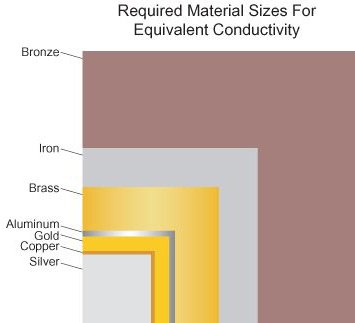
Copper/brass/bronze: Alloys of copper have superior strength and adequate flexibility compared to Copper. But they are not nearly as good a conductor as pure copper (varies from 28 IACS to as low as 7 IACS depending on the alloy).
Aluminium is strong and lightweight, but due to its higher resistance is not preferred in audio. (61 IACS)
Silver: Considered as one of the best conductors, due to its cost is rarely used as a conductor. (105 IACS)
Gold: Gold is not as good a conductor as Copper, but close in the spectrum, due to cost and its non-corrosive it is sparingly used only in high-end equipment, where oxidation may be a problem. Often, connectors are plated with gold to avoid corrosion, but you won’t find gold wires. (70 IACS)
IACS is the abbreviation for International Annealed Copper Standard, and the number preceding “IACS” is the percentage of conductivity a material has relative to copper, which is considered to be 100% conductive.
Wires may be a single-solid, stranded or braided.
Single solid wires have, as the name suggests a single solid conductive metal rod of desired gage (thickness) and length.
Stranded wires are thin electrical conductors that are twisted together into a unified bunch. These naked bunches can be coated with a non conductive plastic to form the wires core. The bunches together which form the wire core act as a single conductor.
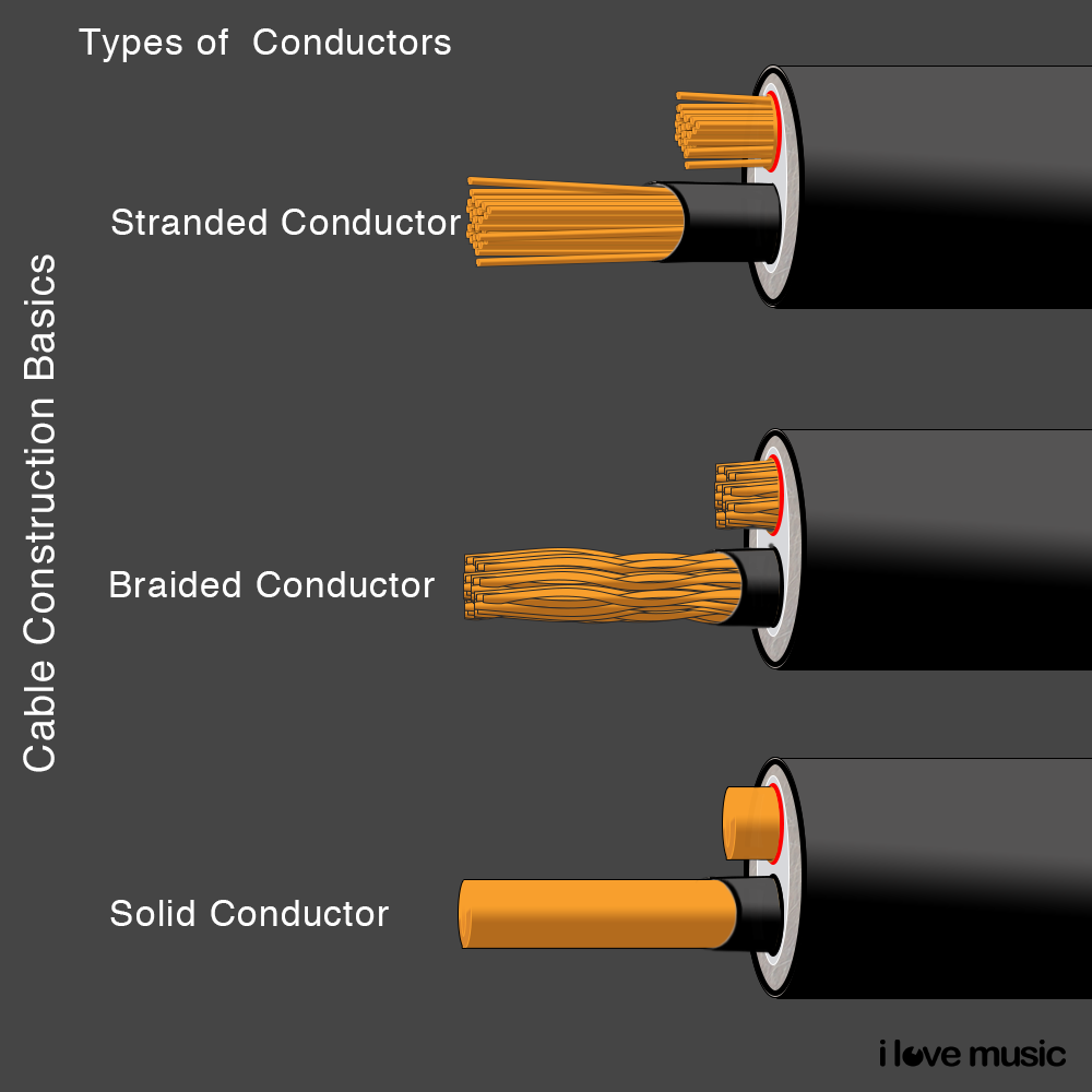
Naked stranded bunches can run parallely alongside one another or braided in a specific pattern based on desired strength, flexibility, technical purposes or just plain aesthetics. More strands means more flexibility and less chances of failure due to nicks and metal fatigue.
Wires VS Cables
We most often use a combination of 2 or more wires that are brought together in one jacket to form what is known as a cable. (A wire is a single electrical conductor vs a cable that has 2 or more wires bound together.)
Note: Multiple conductors that have no insulation around would be classified as a single conductor and not a cable. These are often used for mechanical & load-bearing purposes rather than electrical or signal transmission and referred to as a wire-rope .
Shielded Vs Unshielded Cables.
Shielded or screened cable refers to a Cable made up of one or more insulated wires encased within a standard conductive layer.
When electricity passes through a metal wire it creates a low electromagnetic field (see: right hand rule). This can cause interference or noise in audio cables especially when audio cables run across electrical wires. Shielding is a conductive casing around the conductive cores. In unbalanced cables which have only 1 conductive core, the shielding itself carries the negative or return path of the signal.

Shielding reduces the impact of electrical noise and outside noise as well as reduces the impact of electromagnetic induction (EMI), Radio Frequency Interference (RFI), crosstalk, etc. Mic level and line level
signals require amplification, and any noise along with it will also be amplified; therefore, shielding is imperative here.
In case of unbalanced cables, the shield also acts as a conductor, but more on that later.
Unshielded cables do not have internal shielding to reduce EMI. Instead, they are designed to cancel out EMI by employing a twisted pair of wires, but this is effective only in short distances.
What is EMI?
EMI or Electro-Magnetic-Induction is the process of generating an electric current with a magnetic field. A magnet generating a magnetic field and an electric conductor are made to move in the relative field, causing the generation of voltage or electromotive force due to the change in the magnetic field. So, since a live wire (a wire through which electric current is passing) also creates a low electromagnetic field, any conductor (wire) within the relative field of it will be affected.
RFI: The disturbance generated by an external source that affects an electrical circuit by electromagnetic induction is called Radio Frequency Interference.
Capacitance is the ability of an electrical system to store an electrical charge. (symbol: C) Any object that can be electrically charged exhibits what is referred to as self-capacitance. Therefore, a wire has self-capacitance. The measure of self-capacitance is Farad
Resistance:
The flow of electricity is based on electrons moving through a conductor. The moving electrons collide with ions present in the metal making it more difficult for the flow of current. This is referred to as resistance.
Impedance:
Relatable and relative to resistance, Impedance is a measure of the opposition to electrical flow, measured in ohms and represented by the symbol Z.
Types of Shielding:
- Braided Shielding
- Wrapped or swerved shield
- Foil Shield
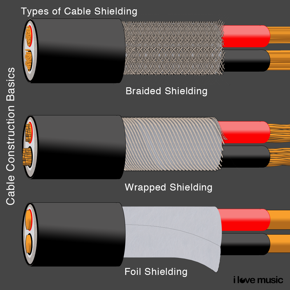
Shielding is very important to maintain a clean sound and keep noise to a minimum. High-frequency noise has very short wavelengths and therefore can easily penetrate loosely braided or wrapped cable shields; shorter the wavelength higher the penetration. Metal Foil Shielding is most effective for this purpose. The obvious question here is why use braided or wrapped shielding at all?
Foil shielding is best used for permanent or fixed wiring and electricals, as they are not very flexible or strong. The shielding deteriorates if flexed often.
Braided and wrapped shielding provides cables with the required flexibility for use on stage in studios and are therefore preferred in mic and instrument cables. Of the two, Wrapped shielding offers greater flexibility than Braided, but the wrap will deteriorate with every flex and can lead to microphone noise.
When the flexing of an audio cable can be heard in the output of the sound, the audio cable is said to be microphonic. Often, unwrapping of the shielding or strands of the braids is touching the conductor within, causing this interference. Therefore, it is important that the cable is tightly bound and a good insulator is used between the conductive layers to ensure that electrostatic noise and microphonic noise are avoided while flexing the cable. Often cables are bound with an outer jacket of rubber or good quality Vinyl to protect it from physical damage and temperature/humidity while maintaining its flexibility.
We use Wires and Cables for 2 main purposes in our studio:
- Transfer of data or signals (for our purposes – Audio Cables)
- Power our devices or transfer electricity
AUDIO CABLES:
For Audio, data transmission can be either in an analogue format or digitally.
- Analogue, where transmission happens through a continuous stream of electricity
- Digital information transmission through binary code, i.e. 1’s and 0’s.
Analog Audio Cables are commonly used in studios and on the stage alike, yet one knows little about them.
Just matching the right connector to the right socket is not enough; one must understand the differences between audio connections and signal types to get quality audio.
Unbalanced and Balanced Cables
There are two types of Audio Cables one can use, Balanced and Unbalanced. Audio Cables have 2 or 3 conductors that run through it, depending on use.
In a balanced Cable, the audio signal is carried using three conductors where one conductor carries the negative, one the positive signal and the third the grounding.
In unbalanced cables, only two conductors are used. One carries positive and the other the negative, which is also the ground.
The advantage of balanced cables is that since negative and ground are separate, there is less chance of noise or radio frequency interference (RFI) in the signal.
Additionally, in balanced cables, the positive and negative signals are exactly the same, except that the polarity of the negative signal is inverted. As the signal travels, the signals individually pick up noise similar to that in unbalanced cables. However, at the opposite end of the audio cable, the signal polarity is re-inverted, leaving the noise picked up (now of opposite polarities) to cancel each other out and therefore produce a clean, strong signal.
Sometimes, a three-conductor cable is used in an unbalanced cable as well. In such a case, the best practice is to fuse the negative and the ground conductors.
Balanced = Signal (+) Signal (-) Ground (.)
Unbalance = Signal (+) Ground(-.)
Colour coding
In dual conductor audio cables, it is common to color code the wires within for easy identification. Red & Black or Black and white.
When Red and Black. The red is always the Live wire or positive with Black carrying the negative or neutral.
When the Black and white wires are used, the same may not stand true of black, however as long as the conductors are connected to the same wires at each end it should not matter.
The fundamentals of Audio cables can be understood through the signals that they carry.
At the end, an audio signal is an electrical current that passes through the audio cable. Its single strength or amplitude is the measure of dB, which is relative to electrical current strength (Volts). Metering these signal strengths can be a bit perplexing, with dBv, dBu, dBm, dBspl, etc. so to keep it simple, dBu is used in professional audio gear while dBV is used in commercial gear. What one also needs to keep in mind is that there are four kinds of Audio signal strengths used in Audio:
- Mic level Signal
- Instrumental level Signal
- Line Level Signal
- Speaker-level Signal
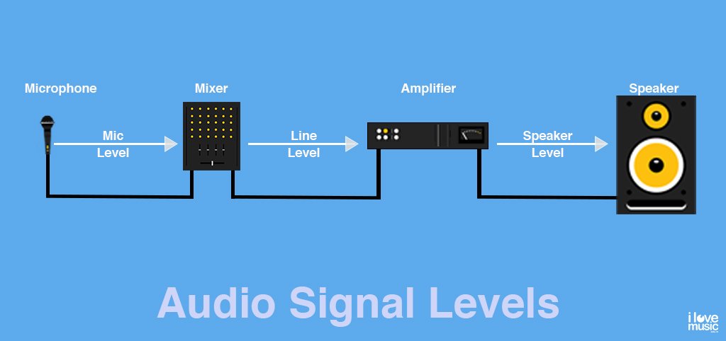
Mic Level Signal is the signal generated by microphones. Microphones emit low voltage output and are considered to be amongst the lowest signals in audio with Voltage ranging from 0.001V to 0.1V. These low level signals are difficult to be read and require a boost or pre-amplification to be introduced into a signal chain for processing. Once passed through a pre-amp it becomes a Line level signal.

If a microphone is plugged directly into a line level input, a very low level will be received which would prompt the gain to be increased allowing a lot of noise to be generated in the signal and is not recommended.
Microphone outputs range from Low-output Mics such as Ribbon and Dynamic microphones to High-output microphones such as Condensers which have amplifiers built right into the microphones. A pre-amp will still be required to bring it to line level.
Instrumental Level signal is the signal generated by instrument pickups, like electrical or bass guitars. Here, the instrument is unable to generate the required strength, though higher than mic level signals. Additionally, the signal produced by the guitar is unbalanced. The Built-in pickups in the instruments do not have the required power and are juiced by increasing gains, adding a lot more noise to the signal. Here, the instrument output transferred via an audio cable to an active DI box (direct input box) acts as a converter for the unbalanced signal, reducing noise to bring the clean signal, which is boosted to a line-level signal for direct use in an audio interface or mixing desk.
By now you must be wondering: what is a Line level signal? since it seems to have a lot of importance.
Line-level signal is the standard signal strength used in audio in the studio and on stage.
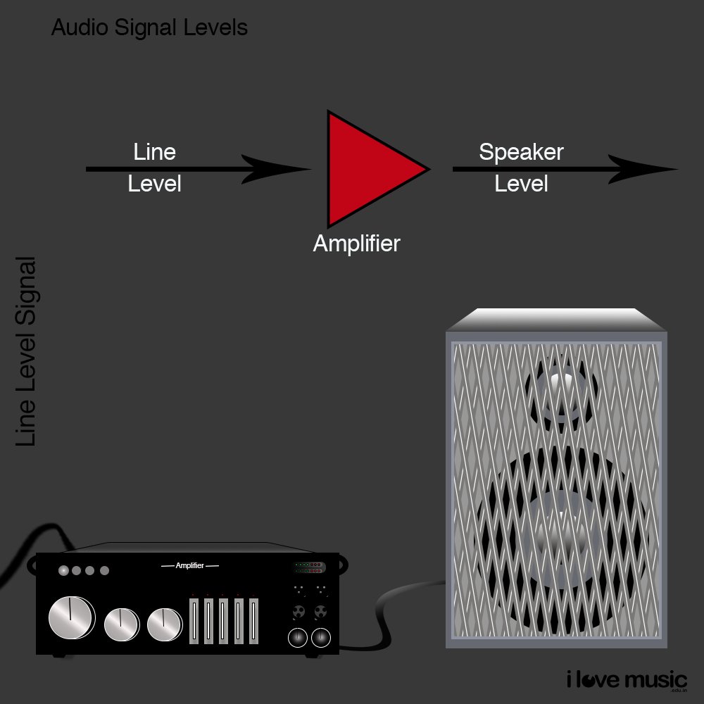
However, this too is also of two kinds. Consumer Line level and Professional Line level signal. The consumer line level is represented in (decibel Volts) dBv while the Professional Line level is represented in (decibel unloaded) dBu, so what’s the main difference?
1 Volt = 0dbV while 0.073Volts =0dBu
dBu was established as the standard measure of signal strength for professional audio in relation to dBspl (sound pressure level), where the calculations are just complex and range from 0 to 20000dB.
The most common nominal level for professional equipment is +4 dBu, which is the line level; while its -10 dBv for consumer equipment, primarily to save on manufacturing cost. Professional line-level equipment is used for studios and stage (equipment like mixing desks, preamplifiers, and signal processing equipment), and all microphone levels and instrument levels are boosted using preamps to get to professional line-level signal strength. If professional live-level equipment is plugged into a commercial line level, it could be dangerous and damage the equipment.
Speaker Level Signal is the hottest of all the signals. It is the signal level post amplification from Line level. An amplifier boosts the signal from line level to speaker level (over 10 volts) providing the desired strength or amplification to drive the speakers. Louder speakers may require even more signal strength 50Volts to 100Volts and require speaker cables for safe transfer.
Mono & Stereo
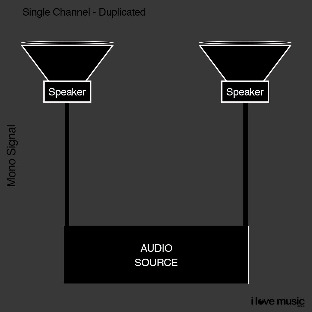
Mono or monophonic sound reproduction refers to a single channel signal where the sound seems as if it is originating from 1 source, normally the sound field being centred.
Stereo or stereographic sound reproduction refers to sound from two or more independent channel signals, where the sound seems as if it is originating from multiple directions. This is more natural sounding and based on technology advancements is the norm having wiped out mono except for in pro-audio.
A mono signal uses only 1 signal and therefore when used or repeated among multiple speakers, it is the same signal repeating. The output would at normal feel like a signal direction of the sound; whereas in stereo as two independent signals are being sent to 2 or multiple speakers, if positioned correctly, the sound would appear to be original from different directions.
Normally 2 signals are sent, simply left and right. Additional stereo signals can be upgraded to form what we refer to as surround sound which is associated with a number: 3.1, 5.1 7.1 etc. Where the first number designates the number of speakers and the .1 refers to a separate bass speaker. For each speaker, an individual wire is used to send an independent balanced signal. But we won’t get into Surround sound here as we are dealing with wires and connectors and not speaker systems.
When I first came across balanced and unbalanced signals, already having a basic understanding of mono and stereo signals, I was totally confused.
Balanced MONO vs Unbalanced STEREO
What one must keep in mind is that for any signal to be generated there must be a positive path and negative path and a ground path. In Balanced cables each of these paths are separate conductor (wires), however, in Unbalanced cables, the negative and ground paths are through a single conductor and only the positive path has an independent conductor.
As already explained, a balanced cable is a 3-conductor cable with namely, positive, negative and earth or shield. For our understanding, for all practical purposes, the signal being passed here would be mono. Then this would be a Balanced MONO signal.
When 2 sets of balanced cables are run parallel, one has a balanced left and the other a balanced right signal to make it a stereo signal. Now, here is where it gets confusing for some.
If the same mono signal is duplicated (split) creating 2 mono signals and running parallel on 2 unbalanced cables, then that does not make it a stereo signal. It will still be a mono signal, just times 2. Here both the signals are the same; and not separate left and right signals (as required for stereo).
If two separate signals, one left and one right run parallel as 2 mono signals on 2 unbalanced cables, then the signal shall be stereo, just not of great quality as noise and interference can be picked up by the cables as they run, degrading the quality of the signal. For short distances, less than a meter this will not be so much of a problem.
It is possible to carry stereo signals on a balanced cable and then split it into 2 unbalanced stereo cables, which is a common practice in the use of headphones.

What is pseudo-stereo
Pseudo -stereo, also known as simulated stereo is a technique of creating a seemingly stereo or two channel output signal from a mono signal. This can be achieved by repeating the same signal on one channel-dry and adding some processing like a micro delay or effects on the other.
For example, mixing a mono guitar amp to two channels with the left side dry (no effects) and the right side processed with a very short delay (a few milliseconds).
Cable Length:
The length of an audio cable is defined by its use, such as speaker cables are normally longer than microphone and instrument cables.
As a rule of Thumb, shorter cables perform better than longer ones, based on electrical resistance when it comes to signal transmission. The longer the cable and the thicker the gauge, the more resistance, so in general, short cables do better – stay under 10 feet for speaker cables and under 8 feet for any other cable use. This is an oversimplification of a more complex topic, but I hope you get the gist of it.
One important factor to note is to always use the same length cables for your right and left speakers to ensure equal impedance values.
Y Cable:
In essence, a Y cable splits a stereo signal into 2 mono signals. When a Balanced connector is split into 2 unbalanced cables, it converts a stereo signal to 2 mono signals. Here, the + conductor of the connector is connected to the positive of the 1st cable, along with the ground connected to the shield, and the – conductor of the connector is connected to the positive of the 2nd cable, with the shield connected to the same ground on the conductor. Y cables are usually TRS to dual TS, but can also be TRS to dual RCA
2 stereo signals can also combine to form one single mono signal as well. When 2 balanced connectors are connected to unbalanced conductor cables, with one unbalanced connector at the other end.
Snake Cable:
Commonly used for both studio and stage, snakes are multichannel audio distribution systems or simply a bunch of shielded pair cables ranging from 8 to 24 or even more, with an overall jacket and possibly even an overall shield. One end of the snake cable ends in a pigtail, with each shielded pair, insulated, brought to an XLR or TRS connector; while the other end terminates in a snake box (a.k.a stage box), which is a junction box mounted with XLR connectors.
The pigtail end connects further to an audio interface or mixing board, while the snake box is left in the recording room or stage for individual microphone/instrument cables to be plugged into.
Used primarily to save time in setup and installation and reduce the mess of wires as well as keep away from electrical/power lines with possible shielding and insulation, thus avoiding noise and crosstalk. It is also important to ensure that snakes are used when transmission is only in one direction; in case a reverse line is required, it should be through a separate cable and not the snake to avoid any interference, for example, a talk-back system.
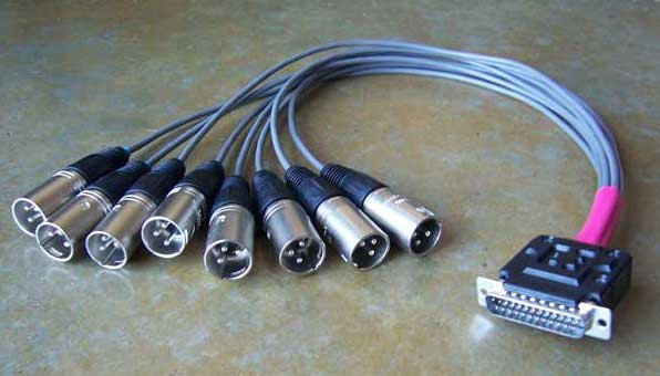
D-Sub Breakout cable:
A D-sub contains parallel rows of pins, usually surrounded by a D-shaped metal shield from which the name is derived. The D-shaped metal Shield provides mechanical support, ensures correct orientation, and may screen against electromagnetic interference.
The D-sub (DIN PIN cables) were originally deployed for computer hardware connections. Though computers rarely use these today, the 25-pin D-sub connector is still occasionally used in recording studios for multi-channel analogue audio and AES digital audio. Mainly a space-saving connector device for high-end boards such as those provided by the Solid State Logic(SSL) desks.
Similar to a snake cable, one side has a pigtail of up to 25 connectors (higher pin connectors are available) while the other end has a D Sub connector that connects directly to the mixing board.
Audio Connectors
A connector is a two-part system that connects, inserts or couples with another to form a conductive connection. One part is referred to as the male or very often the “jack”, while the other is the female, as the male is inserted or coupled with it to form the connection.
So an audio cable could have two male connectors at either end or females or could have one male and the other female, subject to its use.
Given a choice, we would rather solder or crimp wires directly to the equipment. However, that’s possible only where the equipment connection is permanent. Where mobility is required, a connector gives us the flexibility to change equipment as and when required. This obviously comes with a price. And that price is “material resistance”, which will lead to noise. As a plug stays plugged in, corrosion and dirt may build up, adding to the resistance. The unplugging-plugging action dissipates some of this resistance build, to some extent, but may add to the loosening of the connector over time due to wear and tear. Connectors, then, would need to be replaced.
If equipment and connections are fixed in a studio, it would be better to have them soldered permanently to avoid this wear and tear. Many high-end studios do just that with permanent equipment; however, it is difficult to connect every instrument and microphone permanently, and this practice is restricted to immovable equipment rather than microphones and instruments. For high-end studios, the highest quality jacks and connectors are used, which are commonly gold-plated.
Use of gold plating in audio: Gold has low initial resistance and is inert so it won’t corrode and lasts for a long time when compared to any other material. Based on this the best connectors are gold-plated.
Common connectors used in audio include:
XLR:
“Invented by James H. Cannon, founder of Cannon Electric in Los Angeles, California (now part of ITT Corporation)” – source Wikipedia. XLR stands for External Line Return. The XLR connector is a circular connector with up to 10 pins, depending on the manufacturer and use. Their cables are used to deliver balanced microphone and line-level signals over long distances, secure from EMI & noise. The most common one used in pro-audio is the three-pin XLR. They are commonly referred to as microphone cables, as the majority of professional microphones use the XLR.
The male XLR connector is usually incorporated in the body of a microphone, while the cable has the female connector. It is common practice in audio to have pins on the plug pointing in the direction of signal flow. XLR cables have male connectors as well as female connectors with the respective opposite sockets in the equipment. XLR has a clip on one side to lock the connection of the plug to the socket to avoid the plug slipping out of the socket when stretched, making it a secure connection.
The XLR plug is constructed in a way so that PIN1 always connects first. This Pin is meant for ground connectors, making sure that equipment is protected from any pops and clicks that can happen, neutralising electrostatic charges before the actual audio conductors are connected.
Phantom power: There are a lot of misconceptions about phantom power. Designed to power microphones without using bulky external power supplies such as the ones required for tube microphones. It is most widely used as a power source for condenser microphones, which have active electronics. You can use a condenser mic without phantom power, however, it is best to always turn phantom power on when you are using the mic so that you can record at optimal levels.
Phantom power is a 48v DC supplied to the microphone on Pins 2 and 3 of the XLR cable, while ground is supplied by Pin 1. It figuratively piggybacks on the AC signal and is invisible in operation.
TS
A TS connector is used for unbalanced audio cables. The TS cable is marked by a single ring on the connector separating its two contact points. Here the Tip is connected to the Positive conductor while the Sleeve is connected to the cable shield which acts as both the negative and ground. In case a 2-core balanced cable is used, the negative and the shield must be fused together before connecting it to the sleeve.
Commonly referred to as an ¼’’ inch jack or a 6.3mm jack based on its size, the TS cable is one of the most common instrument cables. It is the standard for Electrical guitar cables and therefore also called a Guitar Jack, and the audio cable is called a Guitar Cable, but is also used in other mainstream musical equipment used for instrument and line-level signals.
Since the tip here would come in contact with the connection first, it is likely that it would cause pops when inserted in a system in operation. You would have therefore noticedthat most professional guitarists will reduce the instrument gain before plugging in.
Points to remember
- 1 channel
- Unbalanced signal
- Mono signal
- Plays on one speaker
TRS:
Originally designed to be used by telephone operators to patch telephone calls on telephone switchboards, the TRS & TS are also referred to as Phone cables. TRS stands for Tip, Ring & Sleeve, based on the three contact points on the connector, separated by two insulator rings.
TRS is a Balanced cable connector capable of Stereo signals (2-channel audio signals).
The Tip connects to the Positive conductor while the Ring is connected to the Negative conductor, with the sleeve connected to the ground.
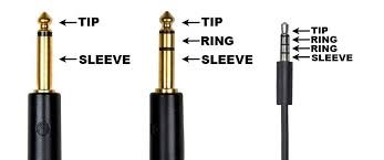
Since it is the same size as the TS jack, the TRS jack also adapts to the name based on its size, adding its functionality: a stereo ¼’’ jack, a 6.5mm stereo jack and a balanced ¼’’ jack
The TRS plug is also used in stereo headphones, so some call it a stereo phone plug as well. But you may have noticed that the signal here is an unbalanced stereo.
Tip refers to the pointed part of the connector till the first black ring insulator. It carries the Right signal
The ring refers to the part between the two black insulated rings that carries the Left signal
The sleeve refers to the part after the second ring carrying the Grounding for both left and right.
(It is interesting to note that though the black rings are common, they can be switched out for other colours as well.)
As explained earlier, a stereo signal needs a left and a right signal. Here the TRS signal is split in the two speakers of the headphone where the Tip signal connects to the right Headphone speaker and the Ring connects to the left headphone speaker with the sleeve as a common ground for both speakers of the headphone. A similar construction is also followed for Y cables.
A smaller 3.5mm TRS jack is also found in practical use in audio. The 1/8″ plug or the stereo minijack is commonly used in commercial audio equipment and more recently in some pro audio equipment in headphones, and is commonly known as a Headphone jack.
A mono 3.5mm jack also exists but is less common.
Points to remember
- 2 audio channels
- Balanced mono signal or unbalanced stereo signal
- Plays on the left and right speakers
TRRS
This is a 3.5mm balanced jack with four conductors. The connectors are assigned to different purposes by different manufacturers and currently, there are no standards. Often used as a headphone jack in smartphones, it has the ability to provide stereo sound quality and adds a microphone channel as seen on wired hands-free devices.
RCA
Developed by the Radio Corporation of America in the 1930’s for radio consoles and later adapted to phonographic record players. The RCA plug is therefore also called the Phono plug as an abbreviation of phonographic. It is meant to be an inexpensive pin plug providing a mono signal, allowing a lot of connectors to be placed in small spaces.
RCA wire is a coaxial cable that provides an unbalanced mono signal and is often used as a pair in pro-audio to provide stereo audio. DJ mixers, Turntables, and CD players, all use RCA connectors.
The cable would have a standard plug on each end, consisting of a male connector, surrounded by a ring to hold the plug in place when coupling with the female connector on the device which would be a hole with a ring of metal around separated by a coloured plastic. The moulding of the male connector would be the same colour as the separator on the female connector to easily match the intended connector couple.
RCA plugs are very common in home audio and home theatre setups. Due to high demand, they are commercially available as pre-moulded with the coaxial cable, as they are small and difficult to connect with the cable.
Normally available as single cables or sold as pairs for stereo audio, they are also found in threes for Audio/Visual use.
The same RCA plug is also used for SPDIF digital connections as well but marked as Orange for easy identification.
Each combination is normally associated with a specific colour combination for easy identification, most commonly:
Audio: Red stereo Right & White for stereo Left sound
Audio/Visual: Red, White, Yellow. Red and White for stereo audio, with Yellow for video signal.
S/PDIF: Orange
RCA connectors are also used for Surround sound in Home theatre systems in commercial audio.
SpeakON
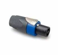
A relatively new connector that is widely gaining popularity as a speaker connection. SpeakON cables are intended solely for use in high-current audio applications, unlike the commonly used ¼’’ & XLR jacks. SpeakON is the trademarked name of Neutrik for “speaker twist connector”. It is mostly used in professional audio systems for connecting loudspeakers to amplifiers.
These connectors come in variants of two, four and eight-pole configurations. The four-pole configuration is the most common. It allows for things like bi-amping (two of the four connections for the higher-frequency signal, with the other two for the lower-frequency signal) without two separate cables. Similarly, the eight-pole connector could be used for tri-amping (two poles each for low, mid and high frequencies with two unused), or quad-amping (two poles each for high, mid, low and sub).
Digital Cables & connectors:
Digital cables are high-speed cables that help transfer data between instruments and computers, where signals are transmitted as 1’s and 0’s. We don’t really need to get into the actual construction or technology behind the cable itself, but rather comprehend the use of it along with its connectors.
But before we get into digital cables, please take note that analogue audio needs to be first converted into digital.
Audio Interface:
The audio interface is one of the most important parts of modern studios. It is a device that converts analogue audio to digital information that a computer can understand and use in the DAW(Digital Audio Workstation). There are three main types of cables used by Audio interfaces to connect the computer or to other equipment: USB, FireWire and Thunderbolt. Analogue audio cables such as RCA, Phono & XLR audio cables bring in the audio signals, and a digital signal is sent out through the digital cable to the computer or to other devices connecting the computer to it, somewhat like a bridge between two signals.
Types of Digital Audio Cable Technology:
- USB: USB stands for Universal Serial Bus. It is a short-distance digital communication cable with speeds up to 1.1 Mbps. – USB was upgraded to USB 2 technology, and speeds were increased up to 480Mbps. It is one of the most common digital connections used in computers and consumer electronics, but would possibly be among the slowest in the modern digital world. – USB3: The upgrade to USB 2, the newer, faster and better USB technology that theoretically has a bandwidth of 5 Gbps. Its socket on devices is either blue in colour or marked with “SS” for “super-speed”. USB connector shapes A ,B & C have no bearing on speed. Shapes were based on the product/ manufacturer. In the same way, USB mini and USB micro were also developed to save space on devices. USB-C was recently launched by Apple and uses the USB 3 technology, so it supports USB 3.1, offering super speed up to 10 Gbps. Just launched is USB 3.2.
- Firewire: Once considered for its superior speeds in digital audio, today FireWire is an old-school technology for digital audio that is really seen. Firewire, also called IEEE 1394, provides data transfer speeds up to 400 Mbps (megabits per second).
- Thunderbolt: Thunderbolt is an interconnect technology developed by Intel in cooperation with Apple. It has super-fast data transfer rates, previously only seen on dedicated PCIe processing cards. Most high-end digital audio equipment today has Thunderbolt ports. Supports fast data transfers with two independent channels of 10Gb/s each. Thunderbolt 2 technology can bond the two channels for a super-fast 20Gb/s. Thunderbolt 3 provides 40Gbps has the same design and can connect to the Apple USB C port. However, the speed of the Apple USB C thunderbolt port is only 10Gbps.
- Midi: Musical Instrument Digital Interface communicates various types of musical information, including notes and velocity from midi devices to virtual instruments on the computer/DAW. The MIDI signal is a relatively high-speed serial data streamMidi signals can now be sent directly via USB, making MIDI connectors almost non-existent in modern music. The midi connectors were traditionally 5-pin DIN connectors.
- SPDIF, also written as S/PDIF digital coax, stands for Sony/Philips Digital Interface. It is used to transmit high-quality digital audio without going through an analogue conversion process. SPDIF sends stereo (two channels) signals using coaxial (RCA) connectors. Easily identified as the orange port on devices, SPDIF is normally marked as a digital port. Its upgrade is the optical SPDIF, which is basically TosLink that uses optical fibres.
- Optical: Optical cables transmit audio signals as pulses of light. Since there is no electricity and only light, there is no electronic magnetic interference, nor any noise in the signal. So basically, you transmit high-quality multichannel audio at the speed of light. Fibre-optic cables offer speeds up to 10 Gbps, but in distances under 500m. A JIS F05 connector is used for fibre optic audio cables. One of the common optical audio cables used is the ADAT optical audio cable developed by Alesis for quick transfer of data for their ADAT machines. It can use eight channels of digital audio data. ADAT is short for Alesis Digital Audio Tape. A similar optical audio cable using the same connector is the TosLink (Toshiba Link), but only uses two-channel formats.
- BNC cables are used in the studio to sync the internal clocks of multiple digital devices whenever two or more are connected. They look identical to a coaxial cable TV connector and are found only in large studios.
- Cat5e cables are Ethernet cables that use type RJ45 connectors. Used for computer LAN (Local area networks) these cables are great to use within the studio to send multi-channel (up to 40 Plus channels)of digital audio, as well as power to equipment if required. Great for lossless transmission on fairly long distances CAT5e cables are great for microphone inputs
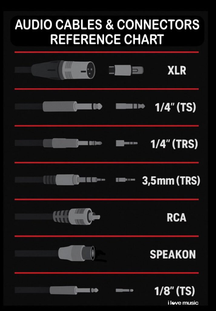
Audio Cables & Connectors Reference Chart
| Cable/Connector Type | Signal Type | Conductors | Shielded? | Balanced/Unbalanced | Common Uses | Notes |
|---|---|---|---|---|---|---|
| XLR | Analogue Audio (Mic/Line) | 3 | Yes | Balanced | Microphones, preamps, mixers | Durable, locking, ideal for long runs |
| TRS (1/4″) | Analogue Audio (Line) | 3 | Yes | Balanced / Stereo | Instruments, balanced line connections | Can carry balanced mono or unbalanced stereo |
| TS (1/4″) | Analog Audio | 2 | Optional | Unbalanced | Guitars, keyboards, instruments | Susceptible to noise over long distances |
| RCA (Phono) | Analog Audio | 2 | Usually No | Unbalanced | Consumer audio, DJ gear | Common for turntables, CD players |
| 3.5mm TRS (Mini Jack) | Analogue Audio (Stereo) | 3 | No | Unbalanced Stereo | Headphones, portable devices | Not ideal for professional setups |
| Y-Cable (TRS to dual TS/RCA) | Reduces cable clutter, centralises routing | 3 → 2×2 | No | Converts Balanced to Unbalanced | Splitting stereo into 2 mono channels | Used for headphone splits, DI routing |
| Snake Cable | Multiple Audio Channels | Varies (8–24 pairs) | Yes | Balanced | Stage boxes, large setups | Reduces cable clutter, centralizes routing |
| D-Sub Breakout | Multi-Channel Audio | 25-pin | Yes | Balanced/Digital | Audio interfaces, SSL desks, patch bays | Compact, high-end studio use |
| Speaker Cable | Power (Speaker Level) | 2 | No | Unbalanced | Amplifier to speakers | Thick gauge, high current, not shielded |
| Digital Cables (e.g., AES/EBU) | Digital Audio | 2 or more | Yes | Balanced | Digital mixers, outboard gear | Often uses XLR or BNC connectors |
Quick Cable Insights
- Balanced cables (XLR, TRS): Best for low-noise, long-distance transmission.
- Unbalanced cables (TS, RCA): Simpler, but vulnerable to EMI/RFI, best for short runs.
- Shielding Types:
- Foil – Best noise protection, poor flexibility
- Braided – Good EMI protection, durable, flexible
- Wrapped/Spiral – Flexible, less durable over time
- Signal Levels:
- Mic Level (0.001–0.1V) → Needs preamp
- Instrument Level (approx. 0.1V) → Needs DI Box
- Line Level (Consumer: -10 dBV, Pro: +4 dBu)
- Speaker Level (10V to 100V) → Needs thick cable
Power Cables:
All devices use electricity as the means of energy to function. Power cables are used to transfer electricity to power these devices.
Almost all pro-audio equipment uses the IEC C13 power cable (IEC cable), from mixing boards, to speakers, to audio-interfaces to even the computer, all use the same power cable connectors. This makes it simple to power devices in the studio as their cables are interchangeable.
IEC C13 is a three-wire power cable. It will have a male three-pin connector (plug) at one end to be plugged into the power source with a female three-hole connector at the other. These connectors are rated for 70 °C and look similar to the IEC C15 cables, which are rated up to 120°C and look similar. Though the C15 can be used to power devices intended for C13 cables, the same is not true in reverse, as the device coupler (socket) on the other end would not accept the cable connector.
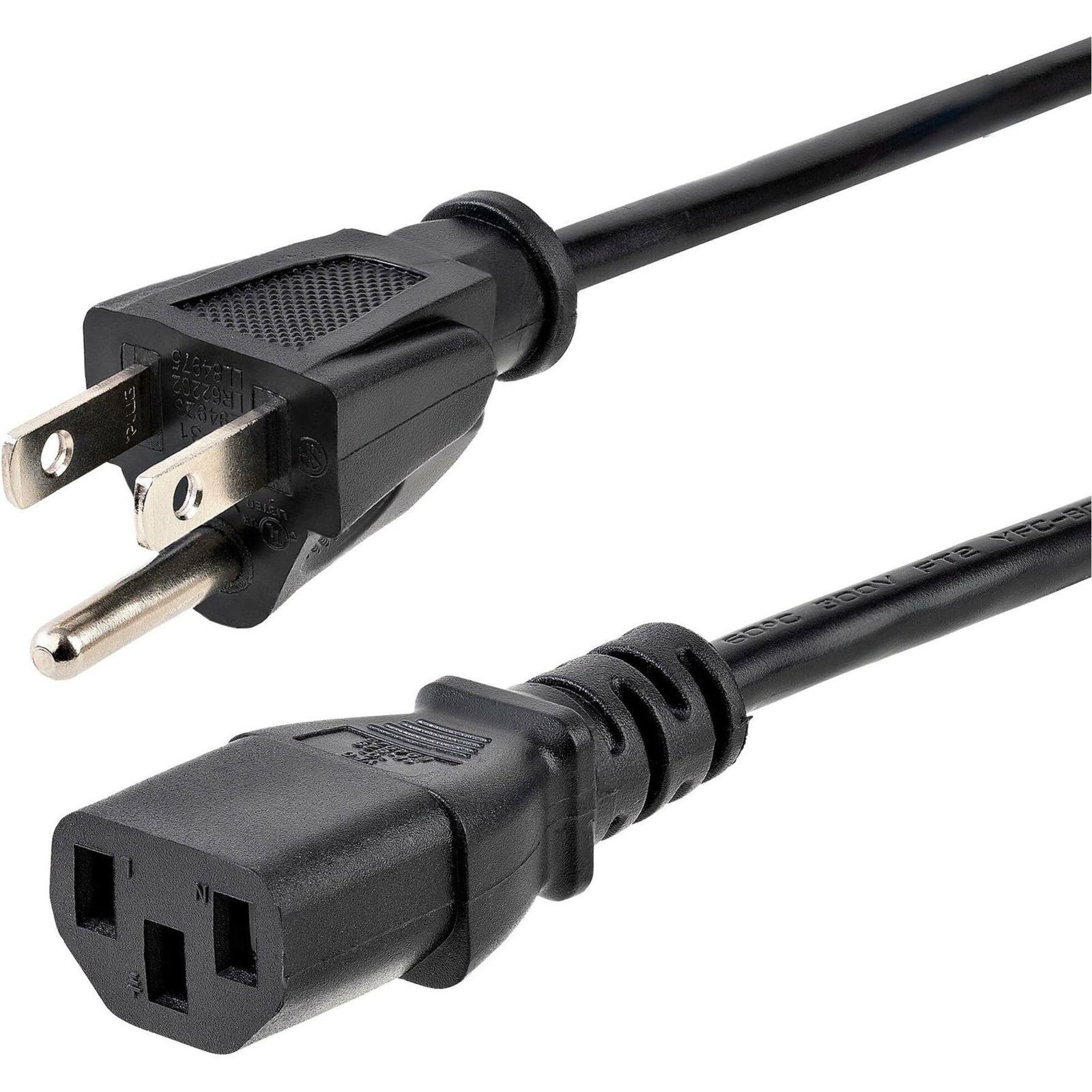
Some audio equipment uses two conductors and a variant of the IEC 13 called IEC 17. Apart from the grounding connection point missing, the cable and connector shape look exactly the same. Although it is always better to use grounding with equipment, some equipment manufacturers, especially for older equipment, do not have grounding.
You may find a different power cable on instruments like drum machines, keyboards, etc. These devices do not have the ability to draw the required current from the regular supply and require an external power adapter to condition the power to function. (A power adapter or AC adapter as it is called, converts AC current to the device requirement of a lower grade DC current). The connectors and pins for these vary based on manufacturer specifications and are too varied to be studied here for practical purposes.
Note: Always use the original adapter that you got with the device. In case you are replacing it due to damage, check the device specification sheet before plugging in any adapter. It is good practice to obtain the adapter specific to the device from the same manufacturer, as they may be different from standard adapters available in the market.
Electrical Wiring in the studio
If you are setting up your studio and wiring it, ensure you use the best quality electrical wire available. Heavy gage three-conductor shielded and insulated cables would be best. It is better to have the gage higher than what is required, although the higher the gage the more it will cost. As we do tend to add equipment to our studios rather than remove, it would be better to accommodate for the additions at the getgo and avoid unnecessary heating of low gage wires which could become a future fire hazard.
The shielding in shielded wires would help avoid compromising any audio cables in the vicinity and reduce any crosstalk or electromagnetic interference from the power cables.
What you should know about electricity:
The standard for electrical wiring color code in India is Red, Black & Green, which was updated to Brown, Blue and green but the old color is still followed in most cases.
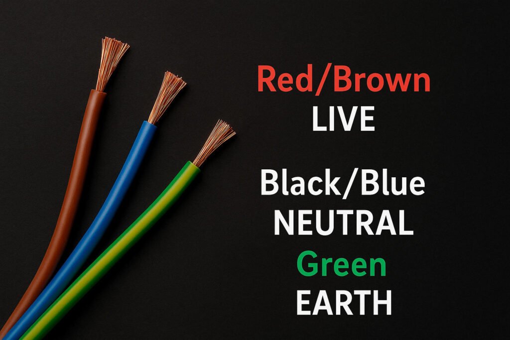
Red/Brown is used for live (or line) power conductors, Black/Blue for neutral and Green for protective earth or ground.
Having a basic understanding of electricity is a good idea when dealing with cables and wires. Standard power supplied in India and most other parts of the world is 220-240 volts, unless you are in the US where 110-120 volts is the standard. Luckily, most pro audio equipment works on dual power. These devices have internal mechanisms to draw the required power they need from the standard power supply available. So we don’t really need to worry, but it would be important to check the equipment before plugging it in.
Additionally, getting good quality power is important for the longevity of pro-audio gear, so ensure power has proper grounding and is conditioned. Filter power to avoid component damage and system glitches can be achieved by using power conditioners and surge protectors in the studio.
To know more about electricity, grounding fuse, surge protection, etc, read the basics of electricity guide for Studio.
Now that we have an understanding of Audio Cables and Power Cables in the studio, here are some tips on maintenance.
Cable Maintenance Tips:
- Do not leave audio cables on the floor. Always secure your cables either in a cable channel, ducting or with masking tape. Cables can prove to be a safety hazard, tripping people in high-movement areas. Also, Audio Cables connectors can be easily damaged by being stepped (yes even metal-cased ones).
- Check your cables: Regularly check for signs of wear and tear. Pests, especially rodents chew the sleeve and damage the integrity of the cable leading to short circuits and loss of property. Individually Cables may not be expensive but when you collectively (check the number of cables you use in the studio) they do cost quite a bit and the equipment they are connected to costs a whole lot more.
- Connector strain: When audio cables are suspended they are susceptible to pulling strain, often from their own cable weight leading to breakage at the connector. It is advisable to provide additional support and keep the bend angle gradual to relieve the strain. Additionally, heat-shrink tubing or Chinese handcuff-type tubing can be employed to provide additional strain relief.
- Cable cleanliness: As cables get old they often get sticky, catching on oil and sweat from human contact or moisture in the air, coupled with dust that settles on them. This over time forms a dirt layer. Cables should be cleaned regularly with a damp cloth to remove this dirt which may harden the rubber sleeve of the cable making it crack and exposing the conductors inside..
- Cable managers: As your studio grows, the number of power and audio cables will increase as well. It’s important to have a system in place to manage this. When cabling your audio and power it is important to separate your audio cables from your power cables. Proper cabling means laying audio cables and power cables as far away from each other as possible. Use cable managers and cable ties, along with labelers to easily identify cables and their connections.
- Storage: When not in use, wrap your cables and store them in a cool, dry place. Cables can be stacked on shelves for long-term storage or hung on holders for easy access to more frequently used cables. Don’t store cables on the ground, avoid pests.
- Wrapping your cables: There is a right way to wrap your cables, ensuring that the cables are not strained and don’t get tangled when being opened for use.

